Calculate transformer losses, efficiency, fault current, and voltage drop from transformer rating, voltage, impedance, load, and power factor.
- All Physics Calculators
- All Electrical Calculators
- Fusing Transformer Calculator
- Transformer Impedance Calculator
- VT Ratio Calculator
- CT Ratio Calculator
- Transformer Voltage Calculator
- Transformer Efficiency Calculator
- Transformer Calculator
Transformer Loss Formula
Transformer loss is the difference between the real power entering the transformer and the real power leaving it. For this calculator, loss is based on voltage, current, and power factor, which makes it suitable for both DC systems and single-phase AC systems using RMS values.
Where:
- TL = transformer loss in watts
- Ii = input current
- Vi = input voltage
- PFi = input power factor
- Io = output current
- Vo = output voltage
- PFo = output power factor
If power factor is not entered, the calculator assumes a value of 1. This is appropriate for DC calculations and for simplified AC estimates when reactive power is being ignored.
Input and Output Power Relationships
The loss equation comes directly from the difference between input real power and output real power:
A positive result means the transformer is dissipating power internally. A result near zero indicates very low loss relative to the measured operating point. A negative result usually suggests inconsistent measurements, incorrect power factor entries, or values taken at different load conditions.
How to Use the Transformer Loss Calculator
- Enter the input current and input voltage.
- Enter the output current and output voltage.
- Add input and output power factor if the system is AC and those values are known.
- Leave PF blank when using a DC approximation or when assuming unity power factor.
- Calculate to find the transformer loss in watts, kilowatts, or megawatts depending on the selected unit.
For the most meaningful result, use measurements taken at the same time and under the same load condition.
What Transformer Loss Represents
The calculator gives the net real-power loss between the transformer input and output. In practice, that loss is usually made up of several components:
- Core loss — caused by hysteresis and eddy currents in the magnetic core; often present whenever the transformer is energized.
- Copper loss — caused by winding resistance and proportional to current; rises with load.
- Stray loss — caused by leakage flux inducing currents in structural parts and conductors.
- Dielectric and miscellaneous losses — generally smaller, but still part of total inefficiency.
This calculator does not separate those loss categories individually. Instead, it reports the total real-power difference implied by your measurements.
Efficiency and Transformer Loss
Transformer loss and efficiency are directly related. Once input and output power are known, efficiency can be calculated as:
As loss increases, efficiency decreases. Even highly efficient transformers still have some loss, especially at higher current levels where winding heating becomes more significant.
Example
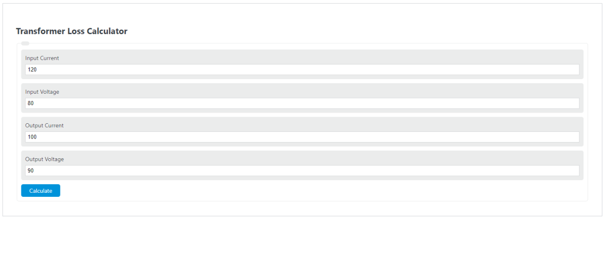
Suppose a transformer has the following measured values:
- Input current = 120 A
- Input voltage = 80 V
- Input power factor = 1
- Output current = 100 A
- Output voltage = 90 V
- Output power factor = 1
First calculate input power:
Then calculate output power:
Now subtract output power from input power:
The transformer loss is 600 W.
Power Factor Notes
In AC systems, power factor matters because voltage and current may not be perfectly in phase. If PF is ignored when the actual system has a lagging or leading load, the calculated loss can be overstated or understated.
- Use PF = 1 for DC calculations.
- Use measured PF values for more accurate AC results.
- If only apparent power is known, convert to real power before interpreting the loss value.
Common Reasons for Unexpected Results
- Negative loss — usually indicates data entry error, mismatched measurement points, or incorrect PF assumptions.
- Very large loss — may result from unit mismatch such as entering kV on one side and V on the other, or A instead of mA.
- Unrealistically low loss — often occurs when PF is assumed to be 1 even though the load is strongly reactive.
Practical Measurement Tips
- Use RMS voltage and current values for AC systems.
- Measure input and output under the same operating condition.
- Confirm unit selections before calculating.
- For lightly loaded transformers, fixed core losses may dominate.
- For heavily loaded transformers, copper losses usually become a larger share of the total.
Single-Phase vs. Three-Phase Use
This calculator uses the direct real-power relationship based on the entered current, voltage, and power factor values. That matches DC and single-phase AC calculations directly. For three-phase systems, determine total real input power and total real output power first, then compare them to obtain loss.
Transformer Loss FAQ
Is transformer loss always present?
Yes. Even with no external load, an energized transformer still experiences core loss. As load current rises, copper loss increases as well.
Why can the output voltage be higher than expected while power is lower?
A transformer can step voltage up or down while still losing some total power internally. Power depends on both voltage and current, and for AC systems also on power factor.
Can this calculator be used for efficiency checks?
Yes. Once the loss is known, it becomes easier to compare input and output power and assess whether the transformer is operating within a reasonable efficiency range for its design and load.