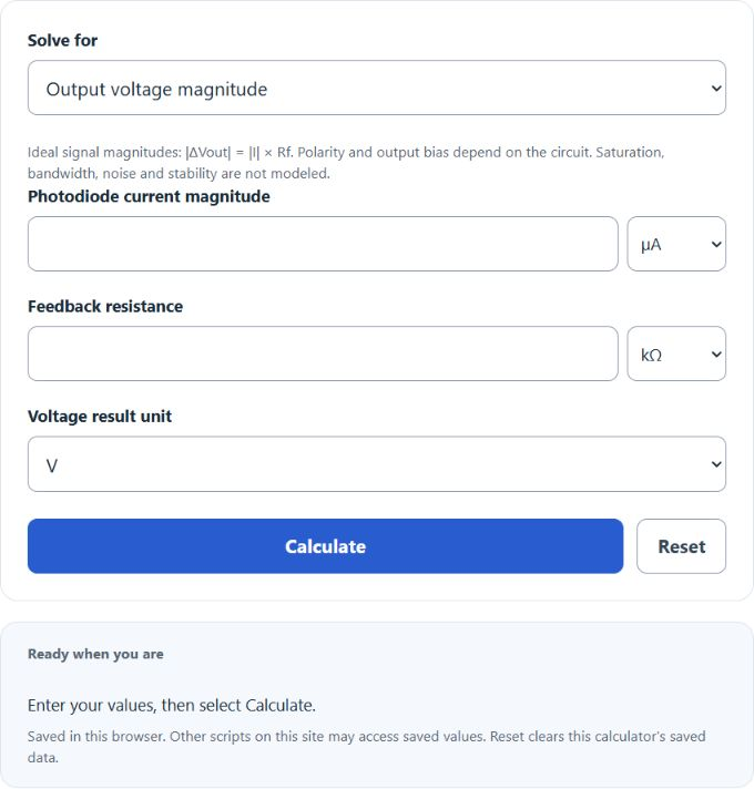
Calculate ideal transimpedance signal magnitude, photodiode current magnitude or positive feedback resistance, or convert incident optical power to current and signal voltage.
Related Calculators
- Dynamic Range Calculator
- 3 dB Rule Calculator
- Average Voltage Calculator
- Capacitor Size Calculator
- All Physics Calculators
Transimpedance Amplifier Formula
The following ideal steady-state equation gives signal magnitudes relative to the amplifier output bias. Polarity depends on current direction and circuit configuration. It does not predict saturation, noise, stability or bandwidth. Optical mode uses I = P × responsivity; use device responsivity at the operating wavelength. Legacy material shortcuts are assumed examples, not universal material specifications.
- Where |ΔVout| is the output signal magnitude relative to its bias (V)
- |IPD| is the photodiode current magnitude (A)
- R_{FB} is the feedback resistor (Ω)
Choose a solve mode and complete the shown fields. Feedback resistance must be positive. Zero current with zero signal does not determine a unique resistance; zero current cannot produce positive signal in this model.
What is a Transimpedance Amplifier?
Definition:
A transimpedance amplifier is an electronic circuit that converts a photodiode current into a proportional voltage using a feedback resistor. It is commonly used in optical sensing and other applications where converting small currents to measurable voltage signals is required.
How to Calculate Transimpedance Amplifier?
Example Problem:
The following example outlines the steps needed to calculate the missing value in a transimpedance amplifier circuit.
First, determine the photodiode current. In this example, assume it is 0.002 A.
Next, identify the feedback resistor. Suppose it is 10000 Ω.
Select Output voltage magnitude and enter those quantities in the corresponding current and resistance units.
Finally, calculate the ideal output signal magnitude using the formula above:
|ΔVout| = |IPD| × RFB
|ΔVout| = 0.002 A × 10000 Ω
|ΔVout| = 20 V. This ideal magnitude is achievable only if the amplifier has sufficient output swing; it is not a guaranteed absolute output voltage.
FAQ
What factors can affect the performance of a transimpedance amplifier?
The performance can be affected by the feedback resistor value, noise characteristics of the amplifier, and the photodiode properties. External interference and power supply stability may also influence its operation.
How do I choose the correct feedback resistor value?
The choice depends on the desired gain, the level of photodiode current, and the trade-off between gain and bandwidth. Higher resistor values can provide more gain but might introduce noise and reduce bandwidth.
Can a transimpedance amplifier be used with any photodiode?
Although transimpedance amplifiers are commonly used with photodiodes, ensuring compatibility between the amplifier’s characteristics and the photodiode’s parameters is crucial for optimal performance.