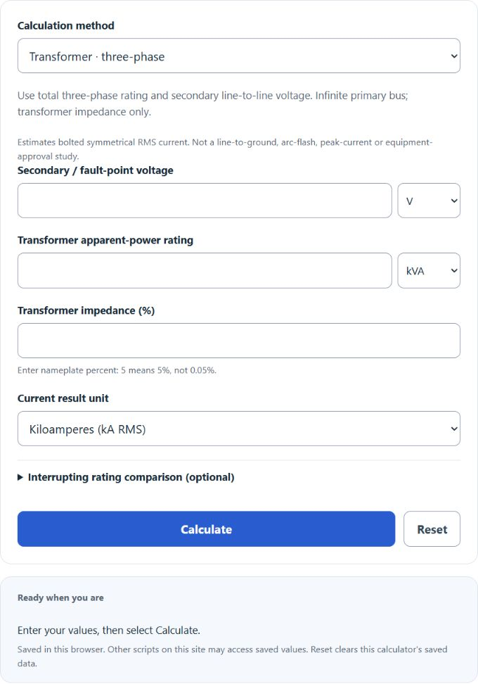
Estimate single- or balanced three-phase bolted symmetrical RMS fault current from transformer rating and %Z or known R+jX. An optional interrupting-rating comparison gives an arithmetic margin only.
- All Electrical Calculators
- All Construction Calculators
- Internal Resistance Calculator
- KVAR Calculator
- Leakage Current Calculator
- Short Circuit Current Calculator
- Inverter Current Calculator
Fault Current Formula
The known-impedance method uses the driving voltage and equivalent impedance magnitude. For a single-phase fault loop, I = V / |Z|. For a balanced three-phase bolted fault, I = VLL / (√3 |Z1|), where Z1 is the positive-sequence per-phase Thevenin impedance. The Eaton short-circuit guide describes transformer and network contributions.
- I or Isc is the bolted symmetrical RMS fault-current estimate (amps)
- V is the voltage across a single-phase loop; VLL is three-phase line-to-line voltage (volts)
- |Z| = √(R² + X²); use complete single-phase loop impedance or three-phase positive-sequence per-phase impedance, in ohms
The transformer method first finds full-load current: VA / V for single phase, or VA / (√3 VLL) for three phase, then divides by %Z / 100. See Schneider Electric’s transformer-current formulas. Use matching full-winding rating and voltage for single phase. This simplified infinite-primary-bus estimate excludes upstream/conductor impedances, other source contributions and tolerance adjustments; it is not a center-tapped line-to-neutral or system ground-fault calculation. The optional rating margin is not a device-selection or certification check.
Fault Current Definition
Fault current is the current that flows when an electrical fault (such as a short circuit) occurs. The available (or prospective) fault current at a point is the maximum current the system can deliver into a fault at that location under stated conditions, and it depends on the source and network impedance and the type of fault.
During a bolted fault the fault-path impedance can be very low, which can make the current very large. In most real power systems, however, the fault current is primarily limited by the total Thevenin/source impedance of the supply (transformers, generators, and conductors), not just the fault’s own resistance.
How to calculate fault current?
Example Problem #1.
Select Known R + jX · single-phase. For this example, use 120 V across the complete fault loop.
Use a complete loop resistance of 0.25 Ω and reactance of 0 Ω, giving |Z| = 0.25 Ω. Leave the optional interrupting rating blank unless a separate arithmetic comparison is needed.
Finally, use Ohm's Law to calculate the fault current.
I = V/Z
= 120/0.25
= 480 amps.
Example Problem #2.
In this next example, we will take a look to see how much a smaller impedance affects the current.
Again, we will use the same voltage as above, 120 V.
Keep the single-phase loop model and set R = 0.05 Ω, X = 0 Ω, so the impedance magnitude is 0.05 Ω.
Using the formula as in example 1:
I = V/Z
= 120/0.05
= 2,400 amps.
This is 5 times the current of example 1.