Calculate electrical heat dissipation, component temperature, required thermal resistance, and water-cooling capacity with metric and imperial units.
- All Physics Calculators
- Specific Heat Calculator
- Cooling Capacity Calculator
- Heat Absorption Calculator
- Heat Rejection Calculator
Heat Dissipation Formulas
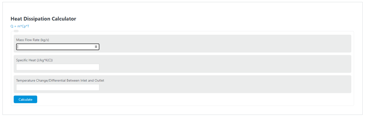
The primary formula for convective heat dissipation through a flowing fluid is:
Where Q is heat dissipated (Watts), m is mass flow rate (kg/s), Cp is specific heat capacity (J/kg·K), and ΔT is the temperature difference between outlet and inlet (K or °C).
When volumetric flow rate is known instead of mass flow rate, the formula expands to:
Where ρ is fluid density (kg/m³) and V̇ is volumetric flow rate (m³/s). This form is common in HVAC and liquid cooling system design where flow is measured in gallons per minute or liters per second.
For heat sink and electronics thermal analysis, the thermal resistance model is used:
Where Rθ is thermal resistance (°C/W), ΔT is the temperature rise above ambient (°C), and P is the power being dissipated (W). Lower thermal resistance means better heat dissipation performance. This value appears on every heat sink datasheet and is the single most important metric for comparing cooling solutions.
Three Mechanisms of Heat Dissipation
All heat dissipation occurs through one or a combination of three physical mechanisms: conduction, convection, and radiation. Each mechanism has its own governing equation and dominates under different conditions.
Conduction is heat transfer through direct molecular contact within a solid or between solids in physical contact. It is governed by Fourier’s Law: Q = k · A · ΔT / L, where k is thermal conductivity (W/m·K), A is cross-sectional area (m²), ΔT is the temperature difference across the material (K), and L is the thickness of the material (m). Conduction is the dominant mechanism inside heat sinks, circuit board layers, and thermal interface materials. The thermal resistance for conduction through a flat slab is R = L / (k · A).
Convection transfers heat between a solid surface and a moving fluid. The rate equation is Newton’s Law of Cooling: Q = h · A · (Ts – Tf), where h is the convective heat transfer coefficient (W/m²·K), A is the wetted surface area, Ts is the surface temperature, and Tf is the bulk fluid temperature. The convective thermal resistance is R = 1 / (h · A). In natural convection with still air, h typically ranges from 5 to 25 W/m²·K. Forced air convection from a fan raises h to roughly 25 to 250 W/m²·K. Forced liquid cooling with water can reach 500 to 10,000 W/m²·K.
Radiation emits energy as electromagnetic waves from any surface above absolute zero. It follows the Stefan-Boltzmann law: Q = ε · σ · A · (Ts⁴ – Tsurr⁴), where ε is surface emissivity (0 to 1), σ is the Stefan-Boltzmann constant (5.67 × 10⁻⁸ W/m²·K⁴), and temperatures are in Kelvin. At low temperature differences typical of electronics cooling (under about 100°C above ambient), radiation contributes roughly 10 to 30% of total dissipation from an exposed surface. Painted or anodized surfaces with emissivity near 0.9 radiate far more effectively than polished metal surfaces with emissivity around 0.05.
Thermal Conductivity of Common Materials
The thermal conductivity (k) of the material in the heat path directly determines how efficiently heat conducts from source to sink. The following reference values are at approximately 25°C.
| Material | k (W/m·K) | Typical Use |
|---|---|---|
| Diamond (Type IIa) | 2,200 | High-power laser submounts |
| Copper (C110) | 401 | Heat spreaders, heat pipes |
| Aluminum (6061-T6) | 167 | Extruded heat sinks, enclosures |
| Aluminum (6063-T5) | 209 | Standard fin-type heat sinks |
| Brass (C360) | 115 | Fittings, heat exchangers |
| Carbon Steel (1010) | 51 | Structural thermal paths |
| Stainless Steel (304) | 16 | Poor conductor, used for insulation |
| Thermal Grease (typical) | 1 to 5 | CPU/GPU interface |
| FR-4 (PCB laminate) | 0.25 | Circuit board substrate |
| Still Air | 0.026 | Natural insulation layer |
Copper conducts heat roughly 15,400 times more effectively than still air. This ratio explains why even a thin layer of trapped air between a chip and a heat sink (without thermal paste) drastically increases junction temperature. Thermal interface materials bridge this gap, typically offering 1 to 5 W/m·K, which is modest compared to metals but vastly better than the air pocket they replace.
Specific Heat and Density of Common Coolants
When using the mass flow or volumetric flow tabs of the calculator, these reference values for common heat transfer fluids at 20°C are useful.
| Fluid | Cp (J/kg·K) | Density (kg/m³) | Common Application |
|---|---|---|---|
| Water (pure) | 4,186 | 998 | Liquid cooling loops, radiators |
| Ethylene Glycol 50/50 | 3,140 | 1,079 | Automotive coolant, freeze protection |
| Propylene Glycol 50/50 | 3,560 | 1,044 | Food-safe cooling systems |
| Mineral Oil | 1,670 | 870 | Transformer cooling, immersion cooling |
| Dielectric Fluid (FC-72) | 1,100 | 1,680 | Two-phase electronics immersion cooling |
| Dry Air (1 atm) | 1,005 | 1.204 | Forced air cooling, ventilation |
| PAO (Polyalphaolefin) | 2,200 | 800 | Military/aerospace liquid cooling |
Water has the highest heat capacity per unit mass of any common liquid coolant, which is why it remains the default choice for most liquid cooling systems. Adding ethylene glycol lowers the specific heat by about 25% but provides freeze protection down to roughly -37°C at a 50/50 mix. For electronics immersion cooling, dielectric fluids like 3M Fluorinert (FC-72) are used because they are electrically non-conductive, though their heat capacity is roughly four times lower than water.
Convective Heat Transfer Coefficient Ranges
The convective heat transfer coefficient (h) varies enormously depending on the fluid and whether flow is natural or forced. Selecting the right cooling method for a given power level depends on understanding these ranges.
| Cooling Method | h (W/m²·K) | Practical Limit (W/cm²) |
|---|---|---|
| Natural convection in air | 5 to 25 | ~0.05 |
| Forced air (low velocity fan) | 25 to 100 | ~0.5 |
| Forced air (high velocity) | 100 to 250 | ~1.5 |
| Natural convection in water | 100 to 1,200 | ~1 |
| Forced water cooling | 500 to 10,000 | ~20 |
| Impingement jet (water) | 10,000 to 100,000 | ~200 |
| Two-phase (boiling) | 2,500 to 100,000 | ~300 |
The practical limit column shows approximate maximum heat flux each method can sustain before the surface temperature becomes unmanageable. A component dissipating 5 W/cm² cannot be cooled by natural air convection alone and requires at minimum a finned heat sink with forced airflow or a transition to liquid cooling.
Thermal Resistance Networks
In real systems, heat passes through multiple layers in series: from the heat source (e.g., a semiconductor junction) through the die, solder, thermal interface material (TIM), heat sink base, fins, and finally to the ambient air or coolant. Each layer has its own thermal resistance, and these resistances add in series just like electrical resistors:
The junction temperature is then: Tj = Tambient + P × Rtotal. For example, an IC dissipating 10 W with Rjunction-case = 1.5 °C/W, RTIM = 0.5 °C/W, and Rheatsink = 3.0 °C/W in a 40°C ambient environment reaches a junction temperature of 40 + 10 × 5.0 = 90°C. If the maximum rated junction temperature is 125°C, the design has 35°C of thermal margin.
When parallel heat paths exist (for instance, heat escaping through both the top and bottom of a BGA package), the combined resistance follows the parallel formula: 1/Rtotal = 1/R1 + 1/R2. Parallel paths always reduce total thermal resistance, which is why adding a heat sink to the PCB backside of a high-power package can meaningfully lower junction temperature even when most heat flows upward.
Heat Dissipation by Application
Electronics and Semiconductor Cooling: Modern processors can dissipate 150 to 400+ W in a package area of roughly 4 to 8 cm². This power density requires multi-layer thermal solutions combining thermal paste (1 to 5 W/m·K), copper heat spreaders (401 W/m·K), vapor chambers, heat pipes, and finned aluminum heat sinks with forced airflow. Data center servers typically allocate 15 to 40 CFM of airflow per server. Liquid cold plates in high-performance computing reduce CPU thermal resistance to roughly 0.05 to 0.15 °C/W, roughly 10x better than air-cooled heat sinks.
Industrial Heat Exchangers: Shell-and-tube and plate heat exchangers handle dissipation loads from kilowatts to hundreds of megawatts. A typical plate heat exchanger achieves overall heat transfer coefficients of 3,000 to 7,000 W/m²·K for water-to-water service, compared to 150 to 1,200 W/m²·K for a shell-and-tube unit with the same fluids. The compact plate design accomplishes this through turbulent flow in narrow channels (2 to 5 mm gap), resulting in units that are 3 to 5 times smaller by volume for equivalent duty.
HVAC and Building Systems: Cooling loads in commercial buildings are typically expressed in tons of refrigeration (1 ton = 3.517 kW = 12,000 BTU/hr). A 10,000 sq ft office space in a warm climate might require 25 to 35 tons of cooling. Chilled water systems circulate water at 6 to 12°C through air handling units, with typical supply/return temperature differentials of 5 to 7°C. The calculator’s volumetric flow tab is directly applicable: a chiller loop flowing 50 GPM of water with a 6°C ΔT dissipates approximately 75 kW.
Automotive and EV Battery Thermal Management: Electric vehicle battery packs generate 5 to 20 kW of waste heat during fast charging and 1 to 5 kW during highway driving. Battery cells must stay within 15 to 35°C for optimal lifespan and performance. Cooling systems use glycol-water mixtures (typically 50/50 ethylene glycol) flowing through cold plates bonded to cell modules. The narrow acceptable temperature window and the sensitivity of lithium-ion cell degradation to temperature make automotive battery cooling one of the most tightly controlled heat dissipation applications in engineering.
Heat Sink Fin Design Factors
For the thermal resistance tab of the calculator, heat sink selection is the most common use case. The thermal resistance of a finned heat sink depends on fin count, fin height, fin thickness, fin spacing, base thickness, material, and airflow conditions.
Fin spacing is critical. For natural convection, optimal fin spacing is typically 6 to 10 mm to allow buoyancy-driven airflow to develop between fins. Spacing them closer chokes the flow and increases thermal resistance. For forced convection, fins can be spaced as close as 1 to 2 mm because the fan provides pressure to push air through narrow channels. Typical production heat sinks have fin aspect ratios (height to gap) between 3:1 and 5:1.
Fin efficiency, defined as actual heat dissipated divided by the heat that would be dissipated if the entire fin were at the base temperature, decreases as fins get taller and thinner. A well-designed forced-convection heat sink targets 40 to 70% fin efficiency. Going below 40% means the fin tips are contributing little and the added material is largely wasted. Copper fins maintain higher efficiency than aluminum at the same geometry because copper’s conductivity (401 W/m·K) is 2.4 times that of aluminum 6063 (167 W/m·K), but copper is 3.3 times heavier and roughly 4 times the cost per volume.