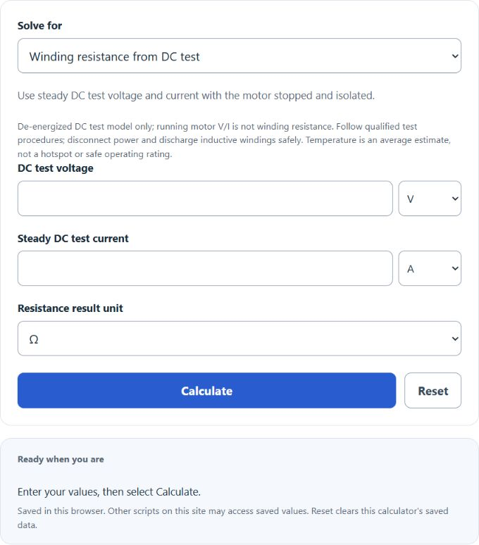
Calculate steady DC winding-test resistance, current or voltage, normalize resistance between temperatures, or estimate average winding temperature from cold and later resistance measurements.
- Nichrome Resistance Calculator
- Wire Resistance Calculator
- All Physics Calculators
- Resistivity Calculator
- Solenoid Force Calculator
- Electric Motor Heat Loss Calculator
- Motor Constant Calculator
Motor Winding Resistance Formula
For a stopped, isolated motor under steady DC test conditions, winding resistance follows the equation below. Running supply V/I does not measure pure winding resistance.
- Where R is the motor winding resistance (ohms)
- V is the voltage (volts)
- I is the current (amps)
For the DC winding-test mode, divide applied DC test voltage by steady test current. Use qualified test procedures, the same winding connection and suitable lead/contact compensation; do not treat this calculator as instructions for selecting a safe test current.
What is Motor Winding Resistance?
Definition:
Motor winding resistance is the conductor resistance of the winding at a stated temperature and connection. Resistance affects copper loss, but torque and motor capability also depend on magnetic design, current control, speed, cooling and rated operating conditions.
A lower winding resistance does not make a 4-hp motor capable of continuously supplying a 5-hp load. Select a motor using manufacturer power, torque, speed, duty and thermal ratings rather than winding resistance alone.
Lower resistance reduces I²R loss only when the same winding current and comparable conditions apply; it does not by itself establish higher overall efficiency or better motor performance. An adequately designed motor should have an appropriate input voltage range, frequency, and full-load currents for reliable operation over its service life.
To achieve this, it is necessary to know details about the power losses in the machine, including voltage drop in cables and current loss in windings, and other factors that affect performance and efficiency, such as ambient temperature and air circulation within the motor enclosure.
How to Calculate Motor Winding Resistance?
The most important thing in calculating Motor Winding Resistance is determining what type of windings are in use. This can sometimes be tricky as each manufacturer may use different types for their motors. It is also important to make sure that there are no short circuits in the winding, as this will also result in an incorrect calculation.
Once you have determined which type of windings are in your motor, you can begin calculating Motor Winding Resistance by using the following equations:
For a uniform conductor: R = ρ L / A. This geometric relation is not a complete slip-ring motor or multi-branch winding model.
Where: R = Resistance (Ω)
L = Length of wire (m)
For temperature normalization use R2 = R1 × (K + T2) / (K + T1); for the resistance-method average temperature use T2 = (R2/R1)(K + T1) − K. The selected models use K = 234.5 °C for copper or 225 °C for aluminum. Constants vary by convention; use the chosen model consistently.
A = conductor cross-sectional area (m²)
ρ = conductor resistivity in Ω·m at the stated temperature; L is conductor length. In the winding-temperature mode, blank ambient omits only rise above ambient. The model accepts 0–200 °C; this is not a motor operating rating. The inferred temperature is an average, not a hotspot; cooling after shutdown can affect the result.