Calculate phasors in rectangular or polar form, perform arithmetic, and convert sinusoids to peak or RMS phasors using degrees or radians.
- All Physics Calculators
- Reference Angle Calculator
- Polar Coordinates Calculator
- Rotation Calculator (new coordinates by rotation)
- Unit Circle Calculator
Phasor Formulas
The core conversion between rectangular (Cartesian) and polar (phasor) form relies on Euler's identity: ejθ = cos θ + j sin θ. This identity is the mathematical foundation that lets engineers move freely between the two representations.
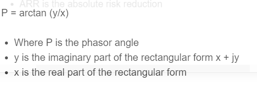
The reverse conversion from polar back to rectangular uses: x = R cos θ and y = R sin θ. The atan2 function (rather than plain arctan) is essential because it returns the correct angle in all four quadrants of the complex plane, handling cases where x is zero or negative.
- Z is the phasor (complex number)
- R is the magnitude (always non-negative), also called the modulus or absolute value
- θ is the phase angle measured counterclockwise from the positive real axis
- x is the real part (in-phase component)
- y is the imaginary part (quadrature component)
- j is the imaginary unit (electrical engineering convention; mathematicians use i)
What Is a Phasor?
A phasor is a complex number that encodes both the amplitude and the phase of a sinusoidal signal at a single known frequency. In AC circuit analysis, a time-domain voltage like v(t) = Vm cos(ωt + φ) is represented by the phasor V = Vm∠φ. The angular frequency ω is factored out because every quantity in the circuit shares the same frequency, so only magnitude and phase offset carry unique information.
This transformation converts differential equations (calculus) into algebraic equations (multiplication and division of complex numbers), which is why phasors are so widely used. A derivative in the time domain becomes multiplication by jω in the phasor domain, and an integral becomes division by jω.
Phasor Reference Table
The table below lists unit-magnitude phasors (R = 1) at standard angles, showing their exact rectangular components. These values repeat in virtually every AC circuit, control system, and signal processing problem. For any other magnitude, multiply x and y by R.
| Angle (degrees) | Angle (rad) | cos θ (x) | sin θ (y) | Rectangular Form |
|---|---|---|---|---|
| 0 | 0 | 1 | 0 | 1 + j0 |
| 30 | π/6 | √3/2 ≈ 0.8660 | 1/2 = 0.5 | 0.8660 + j0.5 |
| 45 | π/4 | √2/2 ≈ 0.7071 | √2/2 ≈ 0.7071 | 0.7071 + j0.7071 |
| 60 | π/3 | 1/2 = 0.5 | √3/2 ≈ 0.8660 | 0.5 + j0.8660 |
| 90 | π/2 | 0 | 1 | 0 + j1 |
| 120 | 2π/3 | -1/2 = -0.5 | √3/2 ≈ 0.8660 | -0.5 + j0.8660 |
| 180 | π | -1 | 0 | -1 + j0 |
| 270 | 3π/2 | 0 | -1 | 0 - j1 |
Notice that 90 degrees corresponds to pure imaginary (j), 180 degrees to a negative real number, and 270 degrees (or -90 degrees) to negative imaginary (-j). In three-phase power systems, the standard phase offsets are 0, 120, and 240 degrees (equivalently -120 degrees), which is why 120 degrees appears as a key row.
Phasors in AC Circuit Analysis
The primary engineering application of phasors is AC steady-state circuit analysis. Every passive component has a phasor-domain relationship that replaces its time-domain differential equation:
| Component | Impedance (Z) | Phase of Current vs. Voltage |
|---|---|---|
| Resistor (R) | R∠0 degrees | In phase (0 degree shift) |
| Inductor (L) | ωL∠90 degrees | Current lags voltage by 90 degrees |
| Capacitor (C) | (1/ωC)∠-90 degrees | Current leads voltage by 90 degrees |
Impedance (Z = R + jX) is itself a phasor-like complex quantity. The real part R is resistance and the imaginary part X is reactance. Inductive reactance (XL = ωL) is positive, while capacitive reactance (XC = -1/ωC) is negative. Ohm's law in phasor form becomes V = IZ, where V, I, and Z are all complex numbers.
This is directly useful for power calculations. The apparent power S (in volt-amperes) is S = VI*, where I* is the complex conjugate of the current phasor. The result decomposes into real power P = |V||I| cos φ (watts) and reactive power Q = |V||I| sin φ (VAR), where φ is the angle between the voltage and current phasors. The ratio P/S is the power factor, and its value ranges from 0 to 1. Industrial facilities with large inductive loads (motors, transformers) often have power factors around 0.7 to 0.85, which utilities penalize because low power factor increases line current without delivering useful work.
Phasor Diagrams
A phasor diagram plots one or more phasors as arrows on the complex plane. The horizontal axis is the real (in-phase) component and the vertical axis is the imaginary (quadrature) component. Each arrow's length represents magnitude and its counterclockwise angle from the positive real axis represents phase.
In a series RLC circuit, the voltage phasor diagram shows VR along the real axis, VL pointing straight up (+90 degrees), and VC pointing straight down (-90 degrees). The total supply voltage is their vector sum. At resonance (ω = 1/√(LC)), VL and VC cancel exactly, leaving only VR, which means the circuit is purely resistive and the power factor equals 1.
In balanced three-phase systems, three voltage phasors of equal magnitude are spaced 120 degrees apart, forming a symmetric pattern. If the phase A voltage is taken as the reference at 0 degrees, phase B sits at -120 degrees (or equivalently 240 degrees) and phase C at -240 degrees (or 120 degrees). The sum of all three balanced phasors is exactly zero, which is why the neutral wire in a balanced system carries no current.
Phasor Arithmetic Rules
Addition and subtraction are simplest in rectangular form: add or subtract the real parts and imaginary parts separately. For example, (3 + j4) + (1 - j2) = 4 + j2.
Multiplication and division are simplest in polar form. To multiply, multiply the magnitudes and add the angles: (R1∠θ1)(R2∠θ2) = R1R2∠(θ1 + θ2). To divide, divide the magnitudes and subtract the angles: (R1∠θ1) / (R2∠θ2) = (R1/R2)∠(θ1 - θ2). This is why the calculator above provides both rectangular and polar modes along with a dedicated operations tab.
Applications Beyond Power Systems
Phasors appear in any domain involving sinusoidal steady-state signals. In RF and telecommunications engineering, signal constellations (QPSK, QAM) are plotted on the complex plane as discrete phasor points, where the angle encodes phase modulation and the magnitude encodes amplitude modulation. In control systems, the Bode plot and Nyquist plot both track how a system's gain (magnitude) and phase shift vary with frequency, which is fundamentally phasor analysis across a sweep of frequencies.
In mechanical vibration analysis, the displacement, velocity, and acceleration of a vibrating mass are phasors related by successive 90-degree phase shifts (velocity leads displacement by 90 degrees, acceleration leads velocity by another 90 degrees). Acoustics, optics (interference patterns), and even quantum mechanics (probability amplitudes) all rely on the same complex-number framework.
One notable modern application is synchrophasor measurement in power grids. Phasor measurement units (PMUs) installed at substations across a grid sample voltage and current phasors at rates of 30 to 60 samples per second, all GPS-time-stamped. Comparing the phase angles between distant nodes in real time reveals grid stress, oscillation modes, and incipient instability far faster than traditional SCADA systems, which report data every 2 to 4 seconds.
FAQ
Rectangular form (also called Cartesian form) expresses a complex number as x + jy, where x is the real part and y is the imaginary part. It maps directly to a point on the complex plane with x on the horizontal axis and y on the vertical axis. This form is most convenient for addition and subtraction of phasors.
A phasor is a complex number that represents the amplitude and phase of a sinusoidal signal at a fixed frequency. It is typically written as R∠θ (polar form) or equivalently as R·e^(jθ) using Euler's formula. Phasors allow engineers to replace time-domain calculus with algebraic operations on complex numbers.
Impedance Z = R + jX is a complex quantity that describes how a circuit element resists AC current. It combines resistance (R, the real part) and reactance (X, the imaginary part). Using phasors, Ohm's law extends to AC circuits as V = IZ, where voltage, current, and impedance are all complex. The phase angle of Z determines whether current leads or lags the voltage.
In electrical engineering, the letter i is already reserved for current (from the French word intensite). To avoid confusion between the imaginary unit and current in circuit equations, engineers adopted j as the standard symbol for the imaginary unit. The mathematics is identical; only the label differs.
Power factor is the cosine of the phase angle between the voltage phasor and the current phasor (cos φ). A power factor of 1 means voltage and current are perfectly in phase (purely resistive load), so all power delivered is real work. A low power factor (for example, 0.7) means a large phase difference exists, indicating significant reactive power that oscillates between source and load without doing useful work. Utilities often charge penalties for power factors below 0.9.