Calculate ripple voltage or minimum filter capacitance for rectifier supplies from load current, capacitance, and full-wave or half-wave 50/60 Hz settings.
- All Physics Calculators
- All Electrical Calculators
- RMS Voltage (VRMS) Calculator
- Peak Voltage Calculator
- Voltage Divider Calculator
- Kirchhoff’s Voltage Law Calculator
- Line to Line Voltage Calculator
- Ripple Current Calculator
Ripple Voltage Formula
Ripple voltage is the residual AC variation that remains on a DC output after rectification and capacitor filtering. This calculator estimates the peak-to-peak ripple voltage for a full-wave rectifier using the standard capacitor-input approximation. In practical terms, ripple increases with load current and decreases as capacitance or source frequency increases.
- Vpp = peak-to-peak ripple voltage
- I = load current in amperes
- f = AC line frequency in hertz
- C = filter capacitance in farads
This calculator uses AC line frequency as the input. For a full-wave rectifier, the capacitor is recharged twice during each AC cycle, so the ripple frequency is double the line frequency.
Rearranged Design Equations
If you know the maximum ripple your circuit can tolerate, these equivalent forms help you size the capacitor or estimate the allowable load current.
How to Use the Calculator
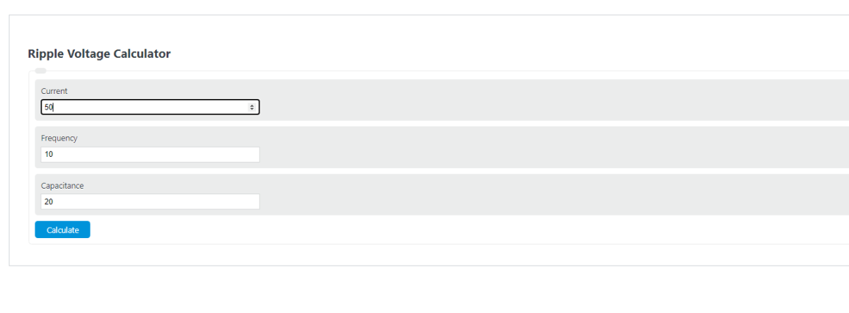
- Enter the load current drawn by the DC side of the circuit.
- Enter the AC line frequency, typically 50 Hz or 60 Hz.
- Enter the total filter capacitance connected across the rectifier output.
- Calculate the result to find the estimated peak-to-peak ripple voltage.
Input Guide
| Input | What It Represents | Effect on Ripple |
|---|---|---|
| Current | Average current demanded by the load from the filtered DC output | Higher current increases ripple |
| Frequency | The incoming AC line frequency feeding the rectifier | Higher frequency reduces ripple |
| Capacitance | Total smoothing capacitance across the output | Higher capacitance reduces ripple |
Example Calculation
Suppose a full-wave power supply delivers 1.5 A from a 60 Hz source and uses a 4700 µF filter capacitor.
This means the DC output rises near each charging peak and then falls by about 2.66 V before the next recharge pulse.
How Each Input Changes Ripple
- Increase current: ripple rises almost proportionally because the capacitor discharges faster between peaks.
- Increase capacitance: ripple falls because the capacitor stores more charge and holds the output voltage up longer.
- Increase line frequency: ripple falls because the capacitor is recharged more often.
- Reduce ripple: common fixes include a larger capacitor, a lighter load, a higher-frequency source, or an added filtering/regulation stage.
Why Ripple Voltage Matters
- Too much ripple can introduce hum and noise into audio circuits.
- Large ripple reduces the minimum instantaneous DC voltage available to the load.
- Voltage regulators may drop out if ripple pulls the input below the regulator’s required headroom.
- Sensitive digital, analog, and communication circuits generally perform better with lower ripple.
Common Unit Conversions
If multiple capacitors are connected in parallel at the output, their capacitances add together, which lowers ripple.
Full-Wave vs. Half-Wave Rectification
This calculator is intended for full-wave rectifiers. A half-wave rectifier recharges the capacitor only once per AC cycle, so ripple is larger under the same load conditions.
Practical Limits of the Estimate
The formula is a fast design approximation. Real circuits can show different ripple because of capacitor ESR, capacitor aging, diode losses, transformer resistance, pulsed or varying loads, wiring resistance, and regulator behavior. For design work, use this result as a strong first estimate and then verify against the actual circuit or measurement data.