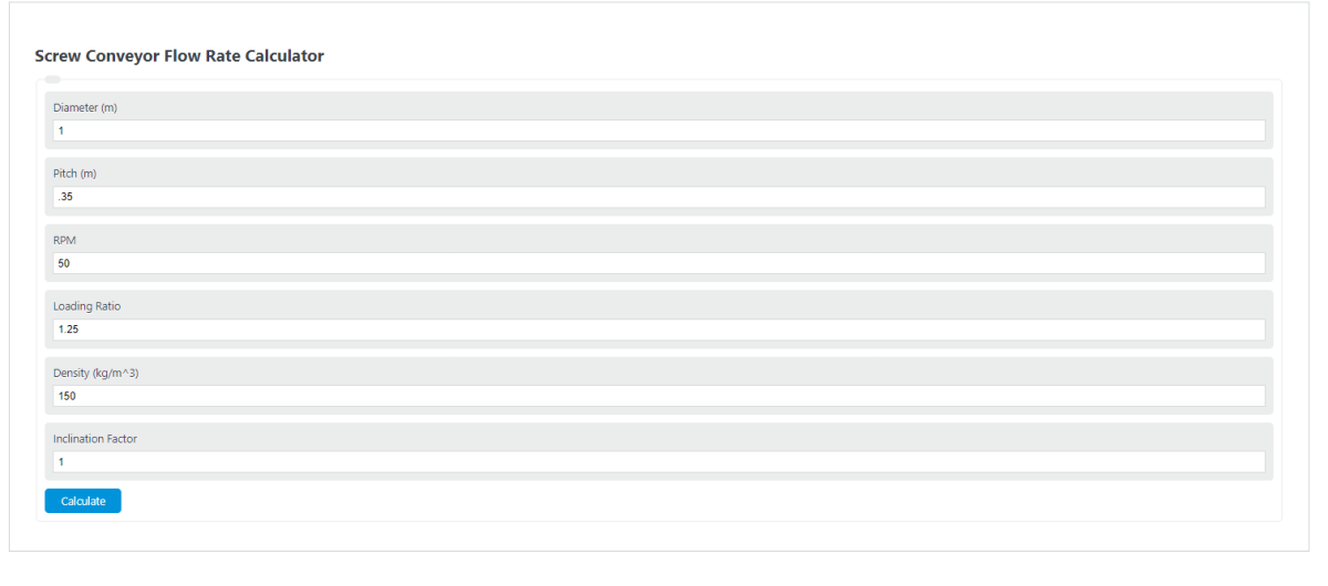
Calculate screw-conveyor mass and volumetric flow from geometry, loading, density, and speed, or reverse-solve the RPM required for a target throughput.
- All Construction Calculators
- Vibrating Screen Capacity Calculator
- Roll Crusher Capacity Calculator
- Inlet Capacity Calculator
- Screw Jack Force Calculator
Screw Conveyor Flow Rate Formula
The screw conveyor flow rate calculator uses the net screw area, pitch, speed, fill factor, bulk density, and inclination factor to estimate mass flow rate.
- \(\dot{m}_{kg/hr}\) = mass flow rate in kilograms per hour
- \(\dot{m}_{lb/hr}\) = mass flow rate in pounds per hour
- \(D\) = screw outside diameter, converted to meters
- \(d_s\) = shaft diameter, converted to meters
- \(S\) = screw pitch, converted to meters
- \(N\) = screw speed in revolutions per minute
- \(a\) = fill factor or loading ratio, from 0 to 1
- \(\rho\) = bulk density, converted to kg/m³
- \(C\) = inclination factor, from 0 to 1
The term \((D^2-d_s^2)\) removes the shaft area from the screw cross section. The pitch and RPM determine how much material is advanced per minute. The fill factor reduces the theoretical full-volume capacity to the actual loaded portion of the screw. Bulk density converts volume flow into mass flow. The inclination factor reduces capacity for upward conveying. A value of 1.0 is typically used for a horizontal conveyor.
Typical Fill and Inclination Factors
Use values that match the material and conveyor layout when available. The ranges below are common starting points for estimates.
| Material behavior | Typical fill factor | Notes |
|---|---|---|
| Free-flowing, non-abrasive material | 0.30 to 0.45 | Often used for grains, pellets, and similar materials |
| Moderately flowing bulk solids | 0.20 to 0.35 | Good starting range for many powders and granules |
| Abrasive, sluggish, or irregular material | 0.10 to 0.25 | Lower loading helps reduce overload and wear |
| Conveyor angle | Typical inclination factor | Capacity effect |
|---|---|---|
| Horizontal | 1.00 | No inclination reduction |
| Slight incline | 0.85 to 0.95 | Small capacity reduction |
| Moderate incline | 0.65 to 0.85 | Noticeable reduction |
| Steep incline | 0.35 to 0.65 | Large reduction, material behavior becomes more important |
Example Calculations
Example 1: Horizontal conveyor in metric units
Given:
- Screw diameter: 0.30 m
- Shaft diameter: 0.05 m
- Pitch: 0.30 m
- Speed: 60 RPM
- Fill factor: 0.30
- Bulk density: 800 kg/m³
- Inclination factor: 1.00
Calculation:
The estimated flow rate is 17,816.8 kg/hr.
Example 2: Imperial inputs with lb/hr output
Given:
- Screw diameter: 12 in
- Shaft diameter: 2 in
- Pitch: 12 in
- Speed: 45 RPM
- Fill factor: 0.25
- Bulk density: 50 lb/ft³
- Inclination factor: 0.80
After unit conversion, the estimated mass flow is about 9,350.6 kg/hr, which is about 20,614.4 lb/hr.
FAQ
What fill factor should you use?
Use the actual loading ratio if you know it. If you are estimating, choose a lower fill factor for abrasive, sticky, sluggish, or irregular materials. Choose a higher fill factor only for free-flowing materials and conveyors designed to carry that loading safely. The calculator limits this value to 0 through 1 because it represents the fraction of the screw cross section filled with material.
Why does shaft diameter reduce the flow rate?
The shaft occupies part of the screw cross section, so that area cannot carry material. The calculator accounts for this by using \(D^2-d_s^2\). A larger shaft leaves less open conveying area and lowers the calculated capacity.
Is the result exact for every material?
No. The result is an estimate based on geometry, speed, loading, density, and inclination. Real flow can change because of material slip, particle size, moisture, aeration, screw clearance, inlet conditions, and discharge restrictions. For design work, compare the result with manufacturer data and material test data when possible.