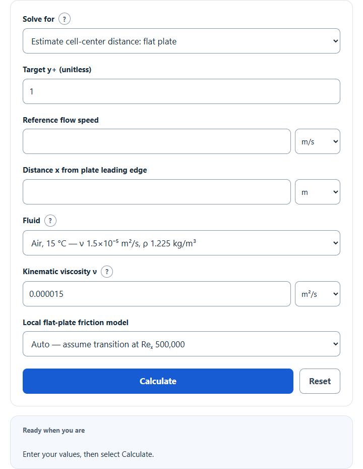
Calculate y+ for CFD, or the first cell height (wall to cell center) for a target y+, from flow speed, wall shear, Cf or friction velocity.
Related Calculators
- Pipe Flow Calculator
- Air Density Calculator
- Velocity Calculator
- Flow to Velocity Calculator
- Pressure to Velocity Calculator
- Volumetric Flow Rate Calculator
- All Math and Numbers Calculators
Y+ Formula
Where the friction velocity is:
And the first cell-center distance for a target y+ is:
- y+ — dimensionless wall distance
- y — distance from the wall to the first cell center (m)
- utau — friction velocity (m/s)
- tauw — wall shear stress (Pa)
- rho — fluid density (kg/m³)
- nu — kinematic viscosity (m²/s)
- U — freestream or reference flow speed (m/s)
- Cf — local skin friction coefficient
For the first-layer estimate, Cf comes from smooth flat-plate correlations: local Cf = 0.664/√Reₓ for laminar flow and local Cf ≈ 0.0592/Reₓ0.2 for turbulent flow, with Reₓ = Ux/ν and x measured from the plate leading edge. The original laminar 1.328 coefficient was a plate-average drag coefficient, not a local wall-shear coefficient. These smooth, attached, incompressible, approximately zero-pressure-gradient correlations are not universal geometry models. The turbulent correlation has the stated range 5×10⁵ < Reₓ < 10⁷; extrapolations are flagged. Auto assumes transition at Reₓ = 500,000, rather than predicting it. These are first-cell estimates only. After running the simulation, recompute y+ from the solved wall shear stress and refine the mesh if needed.
Reference Values
Typical y+ guidance depends on the solver and wall treatment; these ranges are not mesh-quality pass/fail criteria:
| Approach | Target y+ | Notes |
|---|---|---|
| Wall-resolved (low-Re, SST k-ω, Spalart-Allmaras) | y+ < 1 | Often targets the viscous sublayer; also verify boundary-layer resolution and solver requirements. |
| Enhanced / blended wall treatment | Solver-specific | Blended/scalable methods differ; consult the selected solver treatment. |
| Standard wall functions | 30 ≤ y+ ≤ 300 | Log-law region. |
| Buffer layer | 5 < y+ < 30 | May be unsuitable for conventional wall functions; blended treatments can differ. |
Typical fluid properties, selectable under Fluid (air at 15 °C; fresh water and seawater at 20 °C; light oil is an example only). Use measured or specified properties for your simulation:
| Fluid | ν (m²/s) | ρ (kg/m³) |
|---|---|---|
| Air | 1.5 × 10⁻⁵ | 1.225 |
| Water | 1.004 × 10⁻⁶ | 998 |
| Seawater | 1.05 × 10⁻⁶ | 1025 |
| Light oil | 1.0 × 10⁻⁴ | 870 |
Example and FAQ
Example. A smooth flat plate at x = 1 m with U = 30 m/s, ν = 1.5e-5 m²/s and target y+ = 1: Reₓ = 2.0 × 10⁶. Local turbulent Cf ≈ 0.00325174, utau ≈ 1.209662 m/s and y ≈ 1.240016 × 10⁻⁵ m = 0.012400 mm. Full orthogonal first-layer thickness is approximately 0.024800 mm. An airfoil pressure gradient can invalidate this flat-plate estimate.
Is y the first cell height or the cell-center distance? y is the distance from the wall to the first cell center. For an orthogonal near-wall prism with its center halfway through the thickness, the full first-layer thickness is about 2y. Check the mesher’s convention.
Should I divide by 2 for a half-channel? No. y is measured from the wall, regardless of channel symmetry.
My solved y+ differs from the estimate. Expected. Flat-plate Cf is a starting point. Choose Check y+ from friction velocity with solved utau = √(|τw|/ρ), or choose Cell-center distance from wall shear for a new target distance. Verify solved y+ and adjust the mesh.
What about pipe flow? Choose Cell-center distance from known Cf or from wall shear; the flat-plate estimate is not a pipe model. Use a pipe correlation appropriate to its Reynolds number, roughness and development. Cf is defined by τw/(ρU²/2), so a Darcy friction factor must be divided by four before entering it. The smooth turbulent Blasius example Cf ≈ 0.079·Re-0.25 is a conditional estimate, not a universal pipe formula.