Calculate recommended feed rate and chip load for router bits by material, diameter, RPM, flutes, and cut depth or tool style adjustments.
- All Construction Calculators
- Drill SFM Calculator
- Surface Speed (SFM) Calculator
- Spindle Speed Calculator
- Cycle Time Calculator
- Countersink Depth Calculator
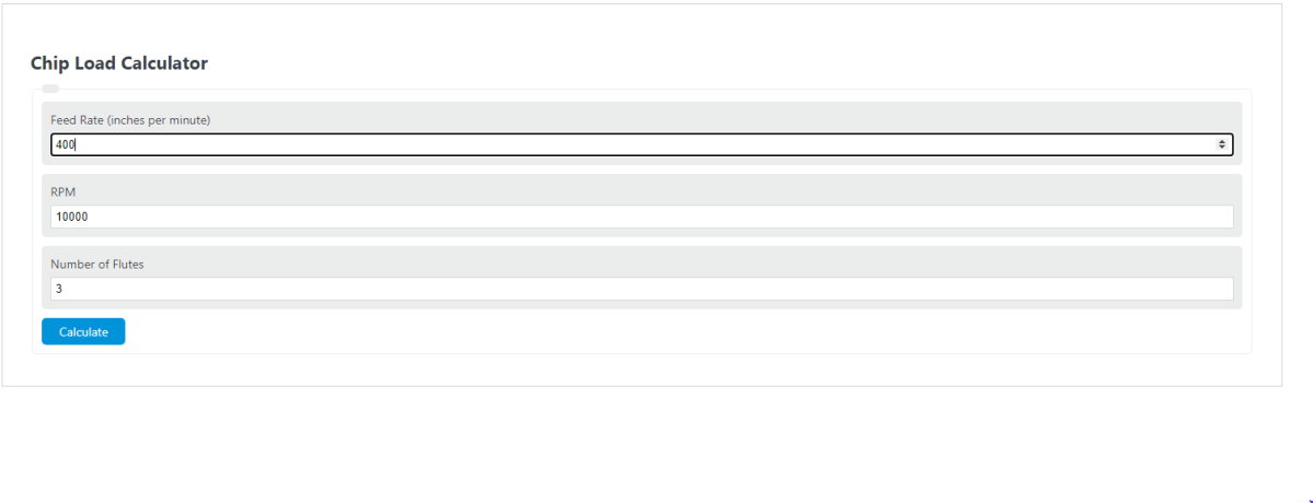
Chip Load Formula
The calculator runs on two rearrangements of the same equation.
Recommended feed mode:
Check chip load mode:
- Feed — feed rate in in/min or mm/min
- ChipLoad — chip thickness per tooth (in/tooth or mm/tooth)
- RPM — spindle speed in revolutions per minute
- Flutes — number of cutting edges on the tool
The recommended values are starting points. Real chip load depends on machine rigidity, tool sharpness, runout, and how well chips clear the cut. Adjust by ear and by inspecting the chips. Powdery dust means the chip load is too low. Burned edges or chatter usually mean it is too high.
The Recommended feed tab pulls a baseline chip load range from the material and tool diameter you select, applies a depth-of-cut factor (down to 0.5× for deep passes) and a tool-style factor (0.7× for downcut grooves), then multiplies by RPM and flutes to give a feed range and midpoint. The Check chip load tab inverts the formula: it divides your feed by RPM and flutes to return the actual chip per tooth, then compares it against the typical range for the selected material and diameter.
Typical Chip Load Ranges
Use these as a starting reference for CNC routers. Values are inches per tooth.
| Material | 1/8 in | 1/4 in | 3/8 in | 1/2 in |
|---|---|---|---|---|
| Hardwood | 0.003–0.005 | 0.009–0.011 | 0.015–0.018 | 0.019–0.021 |
| Softwood | 0.004–0.006 | 0.011–0.013 | 0.018–0.020 | 0.021–0.023 |
| MDF | 0.004–0.007 | 0.013–0.016 | 0.020–0.023 | 0.025–0.027 |
| Plywood / laminate | 0.004–0.006 | 0.010–0.013 | 0.017–0.020 | 0.021–0.024 |
| Acrylic / plastic | 0.002–0.004 | 0.004–0.007 | 0.006–0.009 | 0.008–0.011 |
| Aluminum (router) | 0.001–0.003 | 0.002–0.005 | 0.003–0.006 | 0.004–0.007 |
How to read the result:
| Symptom | Likely cause | Fix |
|---|---|---|
| Fine dust, burning | Chip load too low | Raise feed or lower RPM |
| Chatter, broken bits | Chip load too high | Lower feed or raise RPM |
| Melted plastic on bit | RPM too high for feed | Drop RPM, use O-flute |
| Fuzzy edges in wood | Dull tool or low chip load | Replace bit or raise feed |
Worked Examples
Example 1: Find the feed rate for hardwood. You have a 1/4 in two-flute upcut bit at 18,000 RPM, cutting at 1× tool diameter depth. The hardwood range for 1/4 in is 0.009 to 0.011 in/tooth. At the midpoint of 0.010:
Feed = 0.010 × 18,000 × 2 = 360 in/min
Start near 360 in/min and adjust from there.
Example 2: Check an existing program. Your file runs at 200 in/min, 16,000 RPM, with a two-flute bit.
Chip load = 200 ÷ (16,000 × 2) = 0.00625 in/tooth
For a 1/4 in bit in MDF (0.013–0.016), this is well below range. Expect heat and dust. Either increase the feed to about 450 in/min or drop the RPM to around 6,500.
FAQ
Why does chip load matter? Each cutting edge needs to take a real bite. If the bite is too small, the tool rubs and overheats. If it is too large, the tool deflects, chatters, or breaks.
Should I change feed or RPM first? Change feed first. RPM affects surface speed and heat. Feed is the fastest way to fix chip load without changing how the bit cuts the material.
Do I reduce chip load for deep cuts? Yes. The depth adjustment in the calculator drops the target by 25% at roughly 2× diameter and 50% at 3× diameter to keep tool deflection in check.
Why are downcut bits adjusted lower? Downcut bits pack chips into the cut instead of evacuating them. Reducing chip load by about 30% helps keep the slot clear and the bit cool.
Are these values for routers or mills? The ranges are tuned for CNC routers and trim routers. Industrial milling machines on metal use different values driven by surface speed in SFM.