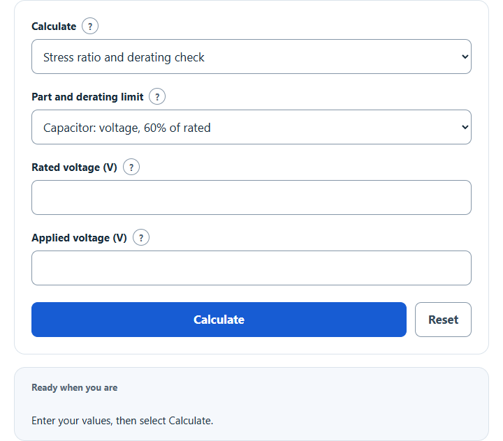
Calculate the stress ratio of a capacitor, resistor or other part against its rating, check it against a derating limit, or derate power for temperature.
- All Physics Calculators
- Derating Factor Calculator
- Power Dissipation Calculator
- Resistor Heat Calculator
- Capacitor Voltage Calculator
- Thermal Dissipation Calculator
- Diode Selection Calculator
Calculator Functions
The calculator compares the voltage, power or current an electronic part sees in a circuit with its rating, and shows whether that stress stays within a derating limit. Select a function to open it in the calculator.
| Function | Use it when | You enter |
|---|---|---|
| Stress ratio and derating check | You have a part and want to know if it is derated enough | Rated value and applied value |
| Minimum rating needed | You know the load and are choosing a part | Applied value |
| Power derating with temperature | A part runs hotter than its rated temperature | Rated power, operating temperature and the two temperatures of the derating curve |
The first two functions ask for the part type, which sets the derating limit: 60% of rated voltage for a capacitor, 60% of rated power for a resistor and so on, or a custom limit from your own design rules. To derate a cable, generator or other equipment with correction factors, use the Derating Factor Calculator.
Component Derating Formulas
| SR | Stress ratio (%) |
| A | Applied voltage, power or current |
| R | Rated voltage, power or current, in the same unit |
Stress ratio and derating check
L is the derating limit in percent of the rating, and Amax is the most the part should see. A part passes when its stress ratio is at or below L. A 50 V capacitor at 25 V has a stress ratio of 50%, inside the 60% limit, and could carry up to 30 V. The preset limits are typical NASA guidelines for flight equipment [1]:
| Part type | Derating limit |
|---|---|
| Capacitors | 60% of rated voltage |
| Resistors | 60% of rated power |
| Semiconductor devices | 50% of rated power, 75% of rated voltage |
| Microcircuits | Supply voltage 80% of rated, 75% of rated power |
| Inductive devices | 50% of rated voltage |
| Relays and connectors | 50% of rated current |
Minimum rating needed
This rearranges the limit to find the smallest rating that keeps a known load within it. A capacitor on a 12 V rail with a 60% limit needs a rating of at least 12 ÷ 0.6 = 20 V, so the next standard rating up is the one to buy.
Power derating with temperature
(Tmax − Tr) [2]
P is the rated power, T the operating temperature, Tr the rated temperature where the datasheet curve starts to fall and Tmax the temperature where it reaches zero. At or below Tr the full rated power applies, and at or above Tmax none does. The traditional resistor curve starts to fall at 70 °C ambient [2]. A 0.25 W chip resistor with a 70 °C to 155 °C curve can carry 0.25 × (155 − 100) ÷ (155 − 70) = 0.162 W at 100 °C.
Limits of This Estimate
- The preset limits are typical guidelines for space-flight parts [1]. Other industries and companies set their own, so use Custom limit when your design rules differ.
- The same guidelines cap junction temperature at 110 °C for semiconductors and 100 °C for microcircuits, and limit inductive devices to 60% of rated temperature [1]. The calculator does not check those.
- The temperature function assumes a straight-line curve, and 70 °C and 155 °C are only typical values. Read both temperatures from the datasheet of the part. Surface-mount resistors may be rated against terminal temperature instead of ambient [2].
- Enter the worst steady value the part sees. Short pulses, surges and ripple have their own ratings and are not covered.
Sources
- NASA Goddard Space Flight Center, Preferred Reliability Practice PD-ED-1201, EEE Parts Derating: stress ratio as applied stress over rated stress, and the typical derating limits by part type (Table 1)
- KOA Speer Electronics, Introduction of the Derating Curves Based on the Terminal Part Temperature: the shape of a resistor power derating curve, the 70 °C ambient starting point, and terminal-temperature curves