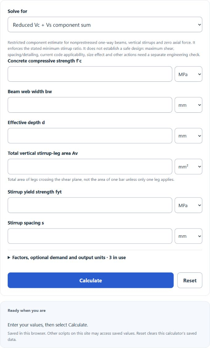
Estimate a restricted one-way beam Vc/Vs component sum or reverse-solve stirrup area and spacing bounds. The stated minimum stirrup ratio is enforced; a complete engineering design check is still required.
Related Calculators
- Concrete Weight Calculator
- Concrete Footing Calculator
- Influence Line Calculator
- Moment Of Resistance Calculator
- Safe Working Load Calculator
- Stress Intensity Factor Calculator
- All Construction Calculators
Concrete Shear Capacity Formula
The following SI-form expression estimates the concrete contribution Vc for the restricted nonprestressed, zero-axial-force component model. It is not the total reduced shear strength or a complete current-code design check. Vertical stirrups and the stated minimum Av/s ratio are required by this implementation.
Variables:
- Vc is the concrete shear component in N for MPa and mm inputs; divide by 1,000 for kN
- fc' is the concrete compressive strength in MPa
- bw is the beam web width in mm; λ is the applicable lightweight factor (1 for normal-weight concrete)
- d is the effective depth of the beam in mm
In MPa, mm and N units: Vc = 0.17 λ √f′c bw d; Vs = Av fyt d / s; the reduced component sum is φ(Vc + Vs). The implementation enforces Av/s ≥ max(0.062 √f′c, 0.35) bw/fyt and restricts f′c to 68.89 MPa and fyt to 420 MPa. US inputs are converted into this SI-form model, so results differ slightly from separately rounded US-code coefficients. See the StructurePoint technical manual, shear provisions.
What is Concrete Shear Capacity?
Shear design includes concrete and reinforcement contributions together with strength reduction, maximum-strength limits, reinforcement spacing, detailing and method applicability. This calculator evaluates selected component equations only. A ratio at or below 100% does not establish structural adequacy. Prestress, deep-beam action, punching, torsion, seismic provisions and axial effects are outside its scope. ACI explains that the 2019 one-way shear provisions differ when shear reinforcement is below the specified minimum; do not use this restricted result as a general current-code design.
How to Calculate Concrete Shear Capacity?
The following steps outline how to calculate the Concrete Shear Capacity.
- First, determine the concrete compressive strength (fc') in MPa.
- Next, measure the width of the beam (b) in mm.
- Then, measure the effective depth of the beam (d) in mm.
- Finally, evaluate the scoped concrete component, add the vertical-stirrup component, and apply the specified reduction factor. Reverse modes take the larger area bound or smaller spacing bound from demand and the enforced minimum ratio. Actual allowable spacing and reinforcement require all separate governing checks.
- Check units and the restricted scope before comparing component arithmetic. A complete design must check Vmax, maximum spacing, anchorage, longitudinal reinforcement, critical section, applicable size effect and the governing code edition.
Example Problem :
Use the following variables as an example problem to test your knowledge.
Concrete compressive strength (fc') = 25 MPa
Width of the beam (b) = 300 mm
Effective depth (d) = 500 mm. With λ = 1, the concrete component is 0.17 × √25 × 300 × 500 = 127,500 N = 127.5 kN. This alone is not a total design shear capacity. For example, Av = 157 mm², fyt = 420 MPa and s = 200 mm give Vs = 164.85 kN and satisfy this model’s minimum ratio of 0.25 mm²/mm. With φ = 0.75, the reduced component sum is 219.2625 kN; omitted design limits still require checking.